
Tập tin gốc (tập tin SVG, 3.000×2.063 điểm ảnh trên danh nghĩa, kích thước: 166 kB)
Miêu tả
|
| Miêu tả |
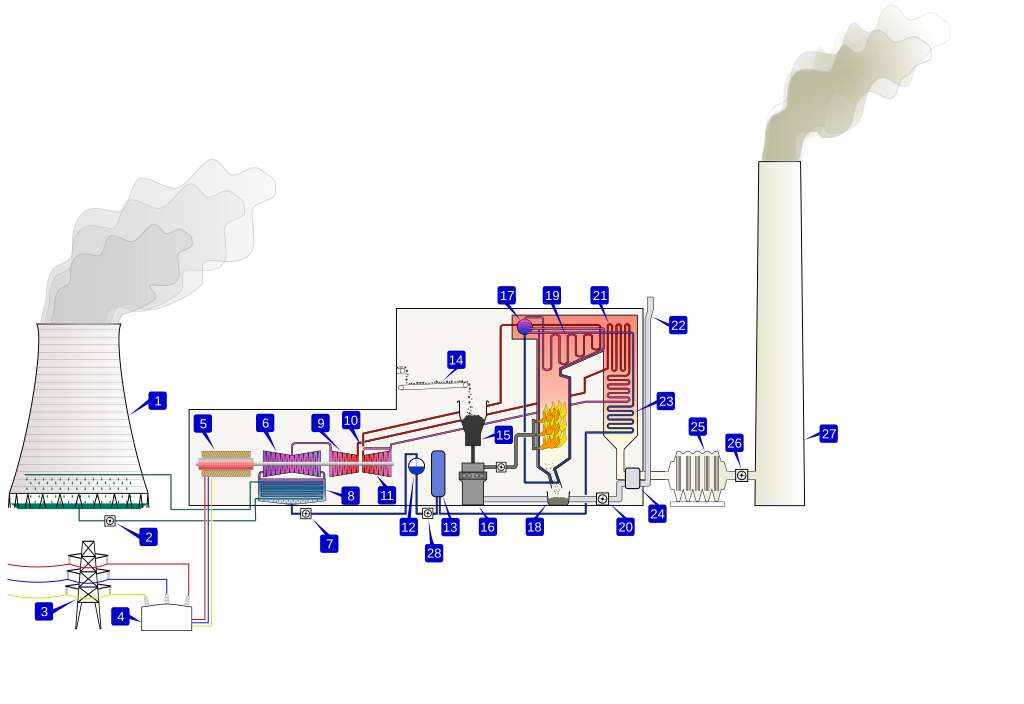
English: A coal-fired thermal power station.
1. Cooling tower. 2. Cooling water pump. 3. Transmission line (3-phase). 4. Unit transformer (3-phase). 5. Electric generator (3-phase). 6. Low pressure turbine. 7. Condensate extraction pump. 8. Condensor. 9. Intermediate pressure turbine. 10. Steam governor valve. 11. High pressure turbine. 12. Deaerator. 13. Feed heater. 14. Coal conveyor. 15. Coal hopper. 16. Pulverised fuel mill. 17. Boiler drum. 18. Ash hopper. 19. Superheater. 20. Forced draught fan. 21. Reheater. 22. Air intake. 23. Economiser. 24. Air preheater. 25. Precipitator. 26. Induced draught fan. 27. Chimney stack. 28. Feed pump. Coal is conveyed (14) from an external stack and ground to a very fine powder by large metal spheres in the pulverised fuel mill (16). There it is mixed with preheated air (24) driven by the forced draught fan (20). The hot air-fuel mixture is forced at high pressure into the boiler where it rapidly ignites. Water of a high purity flows vertically up the tube-lined walls of the boiler, where it turns into steam, and is passed to the boiler drum, where steam is separated from any remaining water. The steam passes through a manifold in the roof of the drum into the pendant superheater (19) where its temperature and pressure increase rapidly to around 200 bar and 570°C, sufficient to make the tube walls glow a dull red. The steam is piped to the high pressure turbine (11), the first of a three-stage turbine process. A steam governor valve (10) allows for both manual control of the turbine and automatic set-point following. The steam is exhausted from the high pressure turbine, and reduced in both pressure and temperature, is returned to the boiler reheater (21). The reheated steam is then passed to the intermediate pressure turbine (9), and from there passed directly to the low pressure turbine set (6). The exiting steam, now a little above its boiling point, is brought into thermal contact with cold water (pumped in from the cooling tower) in the condensor (8), where it condenses rapidly back into water, creating near vacuum-like conditions inside the condensor chest. The condensed water is then passed by a condensate pump (7) to a deaerator (12), then pumped by feedwater pump (28) and pre-warmed, first in a feed heater (13) powered by steam drawn from the high pressure set, and then in the economiser (23), before being returned to the boiler drum. The cooling water from the condensor is sprayed inside a cooling tower (1), creating a highly visible plume of water vapor, before being pumped back to the condensor (8) in cooling water cycle. The three turbine sets are sometimes coupled on the same shaft as the three-phase electrical generator (5) which generates an intermediate level voltage (typically 20-25 kV). This is stepped up by the unit transformer (4) to a voltage more suitable for transmission (typically 250-500 kV) and is sent out onto the three-phase transmission system (3). Exhaust gas from the boiler is drawn by the induced draft fan (26) through an electrostatic precipitator (25) and is then vented through the chimney stack (27).Русский: Схема ГРЭС на угле: 1 — градирня; 2 — циркуляционный насос; 3 — линия электропередачи; 4 — повышающий трансформатор; 5 — турбогенератор; 6 — цилиндр низкого давления паровой турбины; 7 — конденсатный насос; 8 — поверхностный конденсатор; 9 — цилиндр среднего давления паровой турбины; 10 — стопорный клапан; 11 — цилиндр высокого давления паровой турбины; 12 — деаэратор; 13 — регенеративный подогреватель; 14 — транспортёр топливоподачи; 15 — бункер угля; 16 — мельница угля; 17 — барабан котла; 18 — система шлакоудаления; 19 — пароперегреватель; 20 — дутьевой вентилятор; 21 — промежуточный пароперегреватель; 22 — воздухозаборник; 23 — экономайзер; 24 — регенеративный воздухоподогреватель; 25 — фильтр; 26 — дымосос; 27 — дымовая труба; 28 — питательный насос. |
| Nguồn gốc | importée de |
| Tác giả | en:User:BillC |
| Phiên bản khác |
|
| SVG genesis | This diagram was created with Adobe Illustrator. |


Giấy phép
| Tập tin này được phát hành theo Giấy phép Creative Commons Ghi công - Chia sẻ tương tự 3.0 Chưa chuyển đồi Tuân theo lời phủ nhận. | ||
| ||
| Thẻ quyền này được thêm vào tập tin trong khi cập nhật giấy phép GFDL. |

|
Bạn có quyền sao chép, phân phối và/hoặc sửa đổi tài liệu này theo những điều khoản được quy định trong Giấy phép Tài liệu Tự do GNU, phiên bản 1.2 hoặc các phiên bản mới hơn được Quỹ Phần mềm Tự do; quy định; ngoại trừ những phần không được sửa đổi, bìa trước và bìa sau. Bạn có thể xem giấy phép nói trên ở phần Giấy phép Tài liệu Tự do GNU. Tuân theo lời phủ nhận. |
References
- (1982) Modern Power Station Practice (vol 1:Planning & Layout; vol 2:Boilers, Fuel & Ash-handling plant; vol 3: Turbines & Auxiliary Equipment ed.), Oxford: Pergamon ISBN 0-08-016436-6
- RWE npower Didcot Power Stations
- Drax Power Ltd archive copy at the Wayback Machine How Drax works
Historique
Date/Time User Dimensions File size Comment (current) 09:04, 29 August 2007 Magicflame (Talk | contribs) 3000×2063 456 KB Reverted to version as of 10:24, 21 June 2006 (revert) 12:12, 21 June 2006 BillC (Talk | contribs) 3000×2063 456 KB Fix issue with text sizing (revert) 10:24, 21 June 2006 BillC (Talk | contribs) 3000×2063 456 KB Coal-fired thermal power station.
| Annotations | This image is annotated: View the annotations at Commons |
Lịch sử tập tin
Nhấn vào một ngày/giờ để xem nội dung tập tin tại thời điểm đó.
| Ngày/Giờ | Hình nhỏ | Kích cỡ | Thành viên | Miêu tả | |
|---|---|---|---|---|---|
| hiện | 05:39, ngày 26 tháng 11 năm 2021 | | 3.000×2.063 (166 kB) | Puck04 | cleanup, less code |
Các trang sử dụng tập tin
Tập tin sau là bản sao của tập tin này (chi tiết):
- Tập tin:PowerStation2.svg tại Wikimedia Commons
Không có trang nào sử dụng tập tin này.